Voltage Source Inverter Circuit Diagram
Voltage inverter using a 555 schematic circuit diagram Inverter current circuit source diagram figure 12+ 3 phase inverter circuit diagram
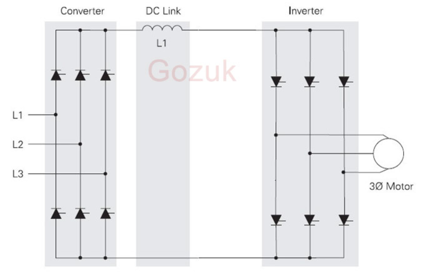
1, Three phase inverter circuit | Download Scientific Diagram
Diagram block inverter watt 200watt inverters circuit mosfet operation 50hz output circuits oscillator electronic control 200w eleccircuit projects high figure Voltage source vsi inverter circuit inverters principle operation working dc power 15 transistor inverter circuit diagram
Inverter 555 circuit ic circuits using power wave diagram bridge output single simplest square type will homemade explored simple parts
Current inverter source motor induction drive fed control circuit controlled operation dc link closedHigh voltage inverter circuit diagram How to make a simple inverter circuit at homeCurrent source inverter : circuit diagram and its advantages.
Electrical video library: v/f control of induction motorInverter conduction inverters switching sine schematics circuitdigest 120° mode inverter – circuit diagram, operation and formulaInverter voltage high current low source circuit diagram 555 timer power schematics circuits ic using electronic.

200w voltage inverter circuit diagram
Inverter voltage schematicInverter circuit diagram simple diy electrical projects electronic wiring electronics schematic pdf using make engineering diagrams power ac dc 12v Operation of 200w inverter circuit diagramInverter voltage circuit ii schematic simple power diagram supply electronic circuits parts dc converter produce negative inexpensive positive dual single.
Inverter as high voltage low current source circuit diagramVoltage source inverters (vsi) operation Inverter circuit diagram 120 mode operation phase three bridge power formula figure shown below electricalVoltage inverter high circuit diagram 3v schematic electronic diy elcircuit dc transistor electrical.

Inverter phase voltage source three circuit vsi power diagram
Power circuit of a three-phase voltage source inverter (vsiInverter voltage circuit source diagram motor figure variable frequency Voltage inverter circuitWhat is current source inverter? definition, control & closed loop.
Electrical video library: v/f control of induction motorCircuit diagram inverter 200w voltage supply power seekic Inverter transistor 3v 220vInverter induction fed.

1, three phase inverter circuit
Simplest power inverter circuit using a single 555 ic .
.
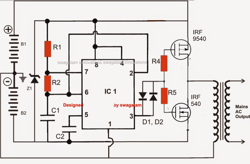

Operation of 200W inverter Circuit diagram | 50Hz oscillator | output

200W voltage inverter circuit diagram - Power_Supply_Circuit - Circuit

1, Three phase inverter circuit | Download Scientific Diagram
ELECTRICAL VIDEO LIBRARY: v/f control of induction motor
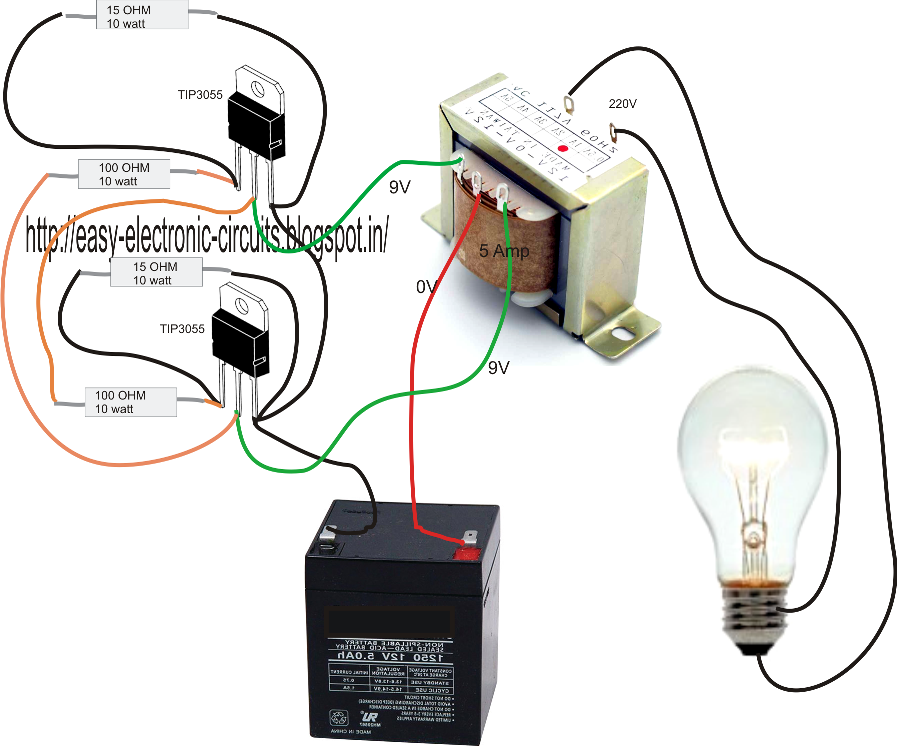
How to Make a Simple Inverter Circuit at Home - ElectricalCoreCircuits

Current Source Inverter : Circuit Diagram and Its Advantages

120° Mode Inverter – Circuit Diagram, Operation and Formula

What is Current Source Inverter? Definition, Control & Closed Loop
